Quickstart: Circuit Generators
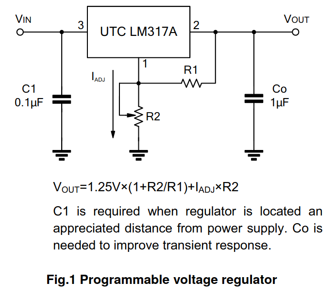
In this tutorial, we'll update the LM317A regulator design from the Quickstart: Your First JITX Design to use a circuit generator when choosing its voltage divider.
NOTE: This Quickstart begins where Quickstart: Organize a Schematic finishes. For your reference, the starting code for the file
main.stanzaand the finished code for this Quickstart tutorial are available.
Tutorial - Circuit Generators
In conventional CAD, we're used to designing every subcircuit/submodule invidivually by hand, separately computing values every time. Often, submodules are nearly identical to each other, but with different values. In these circumstances, we can use circuit generators, which are just functions that return pcb-modules (circuits), to design a circuit one time using input parameters, and then use that design for many different parameters.
You can imagine using circuit generators for all kinds of similar subcircuits:
- voltage divider
- LDO module
- indicator LED with ballast resistor and pulldown
- more
JITX and OCDB have a number of circuit generators built in that you can call. Also, you can define any circuit generator you need.
In this tutorial, we'll use the built-in voltage-divider circuit generator to improve our LM317A implementation.
NOTE: Some of the code block changes rely on later changes to work. If the project doesn't build at some point throughout the tutorial - don't worry. Keep working through the tutorial, and everything should build after making the subsequent changes.
1. Module Properties - Datasheet Values of the LM317A in Code
We're going to need to query electrical properties from the LM317A component in order to write our circuit generator (you can Ctrl+Click in VS Code to go to definition of this component and see which properties are modeled). For example, a property that we will use later in this guide is called property(lm317a.adj-current) which fetches the property named adj-current from the module instance named lm317a. Here is a list of the properties associated with the LM317A, which you can find by looking at the source code of the LM317A:
(Don't copy-paste this block):
  property(self.rated-temperature) = min-max(-40.0 85.0)  ; rated temperature range (in C) for this component
  property(self.reference-voltage) = min-typ-max(1.20, 1.25, 1.3)           ; reference voltage range in Toleranced type from the datasheet
  property(self.minimum-load) = 4.5e-3                                      ; minimum current (A) for proper operation of the regulator
  property(self.adj-current) = 50.0e-6                                      ; expected current (A) for the voltage feedback divider
  property(self.max-current) = 1.5                                          ; maximum current (A) that the regulator can supply to the load

  eval-when has-property?(self.input.voltage) and has-property?(self.output.voltage) :
    val v-out = typ-value(property(self.output.voltage))
    ; Set voltage limits based on figure from page 5.
    property(self.input.power-pin) = ocdb/utils/property-structs/PowerPin(min-max(v-out + 5.0, v-out + 40.0))  ; this property is only set when the input has a valid `voltage` property
2. Adding a Circuit Generator - A Better Voltage Divider
The voltage divider in lm317a-regulator must keep the reference voltage within the specified range given by output-voltage:Toleranced. The voltage divider solver accepts Toleranced arguments and can solve this problem for us. Calculations that we usually do in spreadsheets or comments on a schematic can be code in JITX, so now we're going to do some math to design this circuit.
First off a sanity check - the reference voltage variance on this LM317A can be a problem (only guaranteed to be 4% accurate). Let's check that the accuracy of this regulator doesn't cause the design to be out of specification. To do so, let's add the following codeblock near the bottom of our lm317a-regulator pcb-module (but above the grouping statements).
  ; How much variability can we expect from the regulator alone?
  val refVoltage = property(lm317a.reference-voltage)
  val inherent-variance = tol+%(refVoltage)
  if inherent-variance > tol+%(output-voltage):
    fatal("Target design accuracy infeasible with LM317A %_ > %_" % [inherent-variance tol+%(output-voltage)])
We can then budget the allowable error for the voltage divider by adding the following codeblock below the code we just added:
  ; Budget variability for the voltage divider
  val target-variance = tol+%(output-voltage) - inherent-variance
Finally we need to compensate for the current that the adj pin can source. We choose 5mA of voltage divider current to reduce the overall perturbation, then estimate how to update the set point to compensate.
Add the following codeblock below the code we just added:
  ; 5mA of voltage-divider current to compensate for regulator adj current
  val divider-current = 5.0e-3
  val adj-current = property(lm317a.adj-current) ; retrieve the property from the component definition
  ; Estimate offset voltage caused by current sourced from adj pin
  val est-v-adj-offset = (typ-value(output-voltage) - typ-value(refVoltage)) / divider-current * adj-current
We feed these parameters into the voltage divider solver, which will find a combination of triply-sourceable resistors that produce a voltage within the specified range (including effects of temperature, TCR, manufacturer tolerance, etc.). Notice that we leave off specifying the tolerance of resistors to use in the divider and let the solver find the optimal tolerance range. Remove the old voltage-divider definition block from the lm317a-regulator and paste the following code at the bottom of the lm317a-regulator block:
  inst output-voltage-divider : ocdb/modules/passive-circuits/voltage-divider(source-voltage = high-voltage, divider-output = adj-voltage, current = current) where :
    val high-voltage = tol%(center-value(output-voltage) - est-v-adj-offset, 0.0)
    val adj-voltage = tol%(typ-value(refVoltage),target-variance)
    val current = divider-current
Make sure you go back and delete the previous definition of output-voltage-divider - we don't need that anymore as we have a new definition.
You can now build the design (Ctrl + Enter). Nice!
Next Step
Add and run checks on this design by following Quickstart: Check a Design.