Landpattern with Arguments
After designing a few boards, it becomes apparent that while most SOT-23's are about the same, there are always some outliers. One manufacturer might claim a slightly different tolerance to another. This typically results in either a land-pattern that isn't necessarily tuned for each part (ie, one land pattern to rule them all) or a plurality of land patterns for each of those cases. Maintaining this library of land patterns quickly becomes a full-time job.
With the ability to write circuits-as-code, we open a new way to support dynamically generated land-patterns. The following is an excerpt from this complete example:
Note - This is a more complex example. But fear not stalwart electron herder, these examples will serve you well as you become more familiar with the JITX environment.
pcb-landpattern SOT-23 (pad-size:Dims, pad-grid:Dims, margin:Double = 0.2) :
  val x0 = x(pad-grid)
  val y0 = y(pad-grid)

  ; Pad Definitions
  val pdef = smd-pad(pad-size)
  pad p[1] : pdef at loc((- x0), y0)
  pad p[2] : pdef at loc((- x0), (- y0))
  pad p[3] : pdef at loc(x0, 0.0)

  ; Find the bounding box around all of the pads.
  val outline = bounds $ Union $ for pd in pads(self) seq:
    pose(pd) * pad-shape(pdef)

  ; Non-Copper Geometry
  val outline* = offset(outline, margin) as RoundedRectangle
  layer(Courtyard(Top)) = Rectangle(width(outline*), height(outline*))
  layer(Silkscreen("f-silk", Top)) = LineRectangle(width(outline*), height(outline*))

  ; Construct the Pin #1 marker in the silkscreen
  val r = 0.15
  val marker = loc((width(outline*) / -2.0) - (3.0 * r), y0)
  layer(Silkscreen("f-silk", Top)) = marker * Circle(2.0 * r)
  ; Reference Designator Helper Function
  ref-label()
If we attempt to visualize this landpattern, we should see:
view(SOT-23(Dims(0.8, 0.5), Dims(1.0, 0.95)))
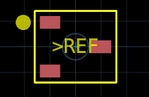
You can still see the skeleton of the static SOT-23 implementation but we've added some new features:
- We've added some arguments to the
pcb-landpatterndefinition that allow us to create a SOT-23 landpattern to our exact specifications. - We compute the bounding rectangle for the pads so that we can construct courtyard shape and silkscreen outline dynamically. This reduces the amount of magic numbers in our design.
- We add a "Pin 1" marker that is placed outside the silkscreen boundary.
Arguments
The arguments are encoded at the beginning of the definition as if this were a normal function definition:
pcb-landpattern SOT-23 (pad-size:Dims, pad-grid:Dims -- margin:Double = 0.2) :
  ...
The pad-size defines the width/height of the pads. The pad-grid defines the "Lead Span" (X) and "Pitch" (Y) of the constructed pads. These are both required arguments.
The margin is the extra space between the external boundary of the pads and the constructed courtyard shape and silkscreen outline. This argument has a default value of 0.2 which means that it is optional argument.
Boundary Rectangle
The core functionality that makes this routine possible is the following line:
  ; Find the bounding box around all of the pads.
  val outline = bounds $ Union $ for pd in pads(self) seq:
    pose(pd) * pad-shape(pdef)
We can break this down into constituent pieces:
for pd in pads(self) seq:
This is a for-loop, like many we have seen before, but this one has something different at the end - a seq instead of a do. seq is an operating function. In particular, seq will convert all of the values returned by the body of this for-loop into a Sequence (iterator).
The pads function provides a sequence of LandPatternPad instances - one for each of the defined pad statements in the landpattern.
The pads function provides a sequence of LandPatternPad instances - one for each of the defined pad statements in the landpattern.
The body of the for-loop consists of:
pose(pd) * pad-shape(pdef)
This takes the shape from the pad definition pdef and then translates it according to the Pose of that pad instance. This translation is so that we don't end up with just 3 rectangles right on top of each other at the origin.
The resultant sequence from the for-loop is passed to the Union shape
constructor function via the Apply Operator, the $ operator.
The Union shape is method of constructing complex shapes. It constructs the geometric union as the name suggests.
The bounds function is similarly invoked via the apply operator. Note how the apply operator allows for chaining a sequence of functions on the output of the for-loop. The bounds function computes the axis-aligned bounding box around the Union shape of all the pads in the land pattern.
That outline result is a Rectangle shape that we can now use to construct our courtyard shape and silkscreen outline and to correctly place the pin-1 marker for our component.