Loc
# Place - how to place a instance or module in JITX
In JITX, we can programmatically place instances or modules on our board with a single line of code.
First, we specify place and the instance that we want to place and then we specify the location. Finally, we specify if we want to place it on the top or the bottom of the board.
## Example placement
inst c : my-component
place(c) at loc(2.0, 3.0) on Top
## loc
The loc statement is for defining a location for placement in JITX. It creates an object describing translation and rotations that can be used to create geometric constraints.
loc statements can be multiplied together (i.e. the transforms can be composed) and used to create trees of kinematic constraints.
pcb-landpatterns and pcb-modules have a right-handed coordinate system with origin at loc(0.0, 0.0, 0.0). Items you place in that coordinate frame will move together. e.g. you can move a landpattern and all the pads stay in the same relative positions. You can place instances in a module, and the relative positions of those instances will remain fixed when you place the module.
### Syntax
loc(1.0, 5.0)
loc(2.0, 3.0, 90.0)
loc(0.0, (- 3.0), (- 90.0)) on Bottom
loc(2.0, 3.0) on Top (relative-to proc)

inside pcb-landpattern :
  pad p[0] : smd-pad(2.0, 1.0) at loc(0.0, 0.0, 90.0) * loc(2.0, 3.0)
  pad p[1] : smd-pad(5.0, 1.0) at loc(2.0, 3.0) * loc(0.0, 0.0, 90.0)

inside pcb-module :
  inst c : my-component
  place(c) at loc(2.0, 3.0) on Top
### Description
loc(1.0, 5.0)Create a pose of (x,y) = (1.0mm, 5.0mm)loc(2.0, 3.0, 90.0)Create a pose of (x,y, theta) = (1.0mm, 5.0mm, 90 degrees)loc(2.0, 3.0, (- 90.0)) on TopCreate a pose of (x,y, theta) = (1.0mm, 5.0mm, -90 degrees), specifying that the component is on Top of the board.loc(0.0, (- 3.0), (- 90.0)) on BottomCreate a pose of (x,y, theta) = (0.0mm, -3.0mm, -90 degrees), specifying that the component is on the Bottom of the board.loc(2.0, 3.0) on Top (relative-to proc)Create a pose of (x,y) = (2.0mm, 3.0), defined from the origin of an instance named 'proc'. This is a relative constraint.
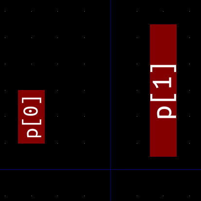
pad p[0] : smd-pad(2.0, 1.0) at loc(0.0, 0.0, 90.0) * loc(2.0, 3.0)
pad p[1] : smd-pad(5.0, 1.0) at loc(2.0, 3.0) * loc(0.0, 0.0, 90.0)
These statements create and place two pads at locations found by composing several poses together. The ordering of poses matters when you are composing them.
The pose loc(0.0, 0.0, 90.0) * loc(2.0, 3.0) first rotates the coordinate system by 90 degrees, and then translates it by (x,y) = (2.0mm, 3.0mm) in the new frame, so that the final pose is (x,y,theta) = (-3.0, 2.0, 90.0)
The pose loc(2.0, 3.0) * loc(0.0, 0.0, 90.0) first translates by (x,y) = (2.0mm, 3.0mm), then rotates the coordinate system by 90 degrees, so that the final pose is (x,y,theta) = (2.0, 3.0, 90.0). Here is the resulting pad geometry (origin of the land pattern is the blue cross):
  inst c : my-component
  place(c) at loc(2.0, 3.0) on Top