NeckDown
There are two types for describing the neck down region of a trace:
NeckDown- This targets Single-Ended tracesDifferentialNeckDown- This targets Differential Pair traces
Outline - NeckDown
defstruct NeckDown :
  trace-width:    Double|False
  clearance:      Double|False
  insertion-loss: Double|False
  velocity:       Double|False

defn NeckDown (--   trace-width:    Double|False = false,
                    clearance:      Double|False = false,
                    insertion-loss: Double|False = false,
                    velocity:       Double|False = false) -> NeckDown :
  ...
All properties of the NeckDown object are optional. If a property is
not provided in the instance, then the pcb-routing-structure property for the current layer will be used by default. These properties act as overrides of the routing structure properties in the neckdown region of a trace.
trace-width- Width of the trace in mmclearance- Minimum "Net to Net" clearance in mm of the tracesvelocity- Signal Propagation Velocity (also known as Group Velocity) of the signals in the neckdown region. This is primarily used for timing constraints. This property is in unitsmm/s.insertion-loss- Insertion Loss per unit distance of the signals in the neckdown region. This property is in units ofdB/mm
Usage - NeckDown
pcb-routing-structure se-50 :
  layer-constraints(Top):
    trace-width = 0.12
    clearance = 0.2
    velocity = 0.19e12
    insertion-loss = 0.008
    neck-down = NeckDown(
      width = 0.085
      clearance = 0.15
      insertion-loss = 0.012
    )
In this example - the neckdown region overrides the width, clearance, and insertion-loss but leaves the velocity property with the default 0.19e12 value.
Creating a Neckdown Region
To activate the neckdown region, we need to convert a section of trace to the "Neckdown" type:
In this video - there is already a control point inserted in the trace. That control point allows us to select the two parts of the trace independently. Selecting the trace on the left side of the control point gives us a "Edit Bar" that allows us to convert the trace from "Normal" to "Neckdown."
Neckdown Features
When we use the neckdown region in the board view, we need to be careful of a few things:
- The neckdown region is like a minimum width - not an explicit width.
- We will only see neckdown behavior if there is at least one obstacle that needs to be avoided.
If there are no obstacles and you convert part of a trace to neckdown, you might see this:
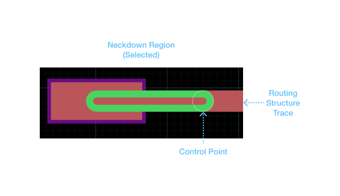
In this view we see a trace that doesn't look any different from the normal routing structure trace. This is expected.
If we introduce an obstacle for the neckdown to avoid we will see different behavior:
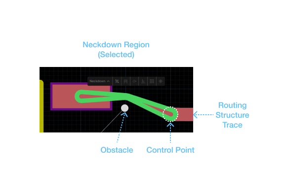
Notice how the width of the trace approaches the minimum width of the neckdown region near the obstacle. The neckdown region isn't fixed width - it is more adaptive than anything. This may be different than what you expect in other tools.
The clearances for the neckdown region are shown below:
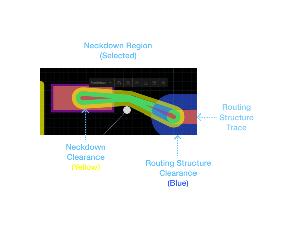
The clearance for the normal routing structure trace and the neckdown region can be different to make it easier to access tight fan-in or fan-out conditions. The blue region is the normal clearance region for the routing structure trace. The yellow region is the clearance for the neckdown region only.
Caution - If the blue region is large, it could conflict with the obstacle. This will result in an unroutable condition.
Outline - DifferentialNeckDown
  defstruct DifferentialNeckDown :
    pair-spacing:   Double|False
    trace-width:    Double|False
    clearance:      Double|False
    insertion-loss: Double|False
    velocity:       Double|False

  defn DifferentialNeckDown (-- pair-spacing:   Double|False = false,
                                trace-width:    Double|False = false,
                                clearance:      Double|False = false,
                                insertion-loss: Double|False = false,
                                velocity:       Double|False = false) -> DifferentialNeckDown :
All properties of the DifferentialNeckDown object are optional. If a property is
not provided in the instance, then the pcb-differential-routing-structure property for the current layer will be used by default. These properties act as overrides of the routing structure properties in the neckdown region of a differential trace.
trace-width- Width in mm of both of the diff-pair conductors.pair-spacing- Spacing distance between the conductors of the differential pair in mm.clearance- Minimum "Net to Net" clearance in mm of the traces. This clearance does not affect thepair-spacingfor the differential pair.velocity- Signal Propagation Velocity (also known as Group Velocity) of the signals in the neckdown region. This is primarily used for timing constraints. This property is in unitsmm/s.insertion-loss- Insertion Loss per unit distance of the signals in the neckdown region. This property is in units ofdB/mm
Usage - DifferentialNeckDown
pcb-differential-routing-structure diff-85 :
  layer-constraints(Top):
    trace-width = 0.12
    pair-spacing = 0.127
    clearance = 0.3
    velocity = 0.19e12
    insertion-loss = 0.008
    neck-down = DifferentialNeckDown(
      clearance = 0.15
    )
In this example - the neckdown region overrides the clearance but leaves all other properties untouched.