Quickstart: Check a Design
In this tutorial, we'll add checks to the regulator design from the Quickstart: Your First JITX Design. These checks add certainty that our circuit will function as expected, and make design work in JITX more reusable. It's easier to use someone else's circuit when that circuit can check itself for correctness.
NOTE: This Quickstart begins where Quickstart: Circuit Generators finishes. For your reference, the starting code for the file
main.stanzaand the finished code for this Quickstart tutorial are available.
Tutorial - Checks
In conventional CAD, we're used to running "Design Rules Checks" (DRC) and "Electrical Rules Checks" (ERC) to ensure that our schematic and board are logical and manufacturable. JITX supports those checks, but it also supports a wide range of checks that go far past traditional DRC and ERC.
You can run built-in checks that check:
- voltage input/output correctness
- pull-ups/pull-downs
- rated temperature compliance
- more
JITX also supports writing your own checks. You can define any requirement you want about your components or modules in code, and then write a check to ensure that requirement is met.
In this tutorial, we'll ensure validity of our implementation of the LM317A module by writing checks for it.
NOTE: Some of the code block changes rely on later changes to work. If the project doesn't build at some point throughout the tutorial - don't worry. Keep working through the tutorial, and everything should build after making the subsequent changes.
1. Adding a Custom Check
As discussed above, we can write custom checks that check for just about anything.
For example, if we wanted to make sure that the component that we imported always has a rated-temperature property defined, we could do so by writing the following custom check:
pcb-check check-rated-temperature (component:JITXObject):

    #CHECK(
    name =                 "Has Rated Temperature"
    description =          "Check that a component has a rated-temperature property"
    condition =            has-property?(component.rated-temperature),
    category =             "Component Data"
    subcheck-description = "Check that %_ has a defined rated-temperature" % [ref(component)],
    pass-message =         "%_ has a property for rated-temperature of %_" % [ref(component) property(component.rated-temperature)],
    info-message =         "%_ does not have a rated-temperature property attached" % [ref(component)],
    locators =             [instance-definition(component)]
    )
And then running it on the LM317A by adding the following codeblock to the lm317a pcb-module definition:
check check-rated-temperature(lm317a)
Compile the design and run run-check-on-design(main-module) in the JITX Shell. Then, open the "JITX: Check Report" panel, and you can see that our custom check ran successfully.
2. Adding a Built-in Check
We handed off the voltage divider design work to a solver. Let's add a check to the lm317a-regulator module so we can trust the resulting output voltage. We now have two real resistors that we can query for properties to determine the actual operating point of the circuit. The Toleranced type does interval arithmetic for us, so the range of operation can be directly calculated. Let's add that code in the lm317a-regulator below the output-voltage-divider:
  ; Calculate the actual offset now that we know the optimized value of the resistors
  val true-adj-offset = adj-current * (property(output-voltage-divider.r-lo.resistance) as Double)
  val vref = property(output-voltage-divider.output-voltage)

  ; Calculate the possible min and max values for the output voltage
  val out = refVoltage * typ(center-value(output-voltage)) / vref + typ(true-adj-offset)
And at last, we use a check from ocdb/utils/checks to make sure that the expected output voltage is within the range specified by adding the following codeblock starting inside lm317a-regulator, near the end but above the net statements:
  ; Make sure that the voltage specification is met
  check ocdb/utils/checks/within?(output-voltage, out)
Run the above with Ctrl + Enter. Then, in the JITX Shell, type run-check-on-design(my-design) to run the check we added to the LM317A circuit.
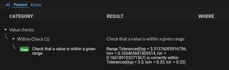
This check will run every time someone using this circuit analyzes their design, so we don't have to be present for every design review on this LM317A.
3. Adding Many Built-in Checks
We can invoke many checks automatically by adding this line of code to the bottom of our top level pcb-module (my-design).
ocdb/utils/checks/check-design(self)
The check-design function in ocdb/utils/checks scrubs through our design looking for properties that identify passives, voltage rails, power pins and digital-io. We can provide these checks with more information by annotating the voltages we know as properties on nets by adding the following codeblock near the end of my-design:
  property(gnd.voltage) = typ(0.0)
  property(vout.voltage) = target-voltage
  property(vin.voltage) = typ(10.0)
Here, the gnd net is 0.0V, vout is our target voltage, and we specify vin to be 10.0V. Based on that, we see new check results (along with our custom check).
Then Ctrl + Enter to re-build, and re-run run-check-on-design(my-design) to run a variety of checks on our design.
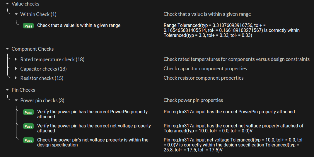
We have derating calculations for all of our passives, manufacturability checks on landpatterns, and a voltage check on the input pin of the regulator.
Note that to pass the derating checks we had to specify the minimum voltage of the capacitors in the LM317A circuit:
  cap-strap(vin, gnd, ["capacitance" => 0.1e-6 "min-rated-voltage" => 25.0])
  cap-strap(vout, gnd, ["capacitance" => 1.0e-6 "min-rated-voltage" => 25.0])
The checking system does not catch every possible error (yet), but it can significantly reduce the risk of our design process by checking the simple stuff. Just adding the properties of power pins and digital-io to JITX as we read datasheets will save quite a few bad boards.
Next Step
Start working with existing design data by importing an Altium design.