pin for Symbols
The pin statement in the pcb-symbol context is used to define the connection points of a schematic symbol.
Signature
; Point Form
pin <Ref> at <Point>

; Annotated Line Form
pin <Ref> at <Point> with:
  direction = <Dir>
  length = <Double>
  number-size = <Double|False>
  name-size = <Double|False>
<Ref>- Name of the pin that will be constructed.- The
Refcan be a standard identifier likeVINor it can be an indexed reference likeD[1],D[2], etc. <Point>- An instance of typePoint.
Usage
The pin statement is used to define the connection points on a schematic symbol. There are two forms for the pin connections:
- Point Form - In this form, the connection point does not have a line associated with it.
- Further, the name and pad number are hidden by default.
- This can be useful for constructing symbols where a line might get in the way or prevent the formation of geometry in the preferred way.
- Annotated Line Form - In this form, the connection point has a line associated with it by default.
Annotated Line Form
Here is an example pin statement in annotated line form:
  pin VIN at Point(0.0, 0.0) with:
    direction = Left
    length = 3.0
    name-size = 0.85
    number-size = 0.85
Here is rendering of the anatomy of a symbol pin:
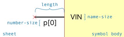
In this view:
- The text
p[0]is thepad ref- this is what pad/hole on the component landpattern that this pin maps to. - The text
VINis thepin ref- this is the name of this pin in the circuit and as shown on the schematic. - This pin has a direction that points to the left.
- Notice that the symbol body is on the right and that the pin's direction is direction it points out from the symbol body.
- The red
Xat the tip of the pin is the connection point where schematic wires will be drawn to/from.
Optional Pad and Pin Ref Text
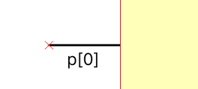
In the annotated line form, you can optionally drop the name-size and number-size parameters from the pin statement. This will cause the pin ref and/or pad ref to be hidden by default:
  pin VIN at Point(0.0, 0.0) with:
    direction = Left
    length = 3.0
    number-size = 0.85
In this case, the pin would be shown as:
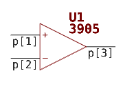
This is useful for constructing more idiomatic schematic symbols where the pin name is not typically shown - for example, in an op amp symbol: