Pin assignment
Just like we improved our amplifier design by removing the need to hard-code details (like the gain resistor resistance), we can write more reusable code by solving for pin assignments rather than hard-coding them. This allows us to easily swap complex components like microcontrollers and FPGAs in our designs.
Very often there are multiple ways to correctly connect the components on a board. i.e. we don't care that this 3rd and 4th pins on our sensor are connected to the 1st and 2nd pins on our microcontroller, but rather that the i2c interface on the sensor is connected to pins on the microcontroller that support i2c. In this section we solve this problem using the support and require statements, and finish our design.
Microcontroller example
Let's start with a small microcontroller we want to connect to our photodiodes, sensor, and a LORA modem. We want to model for a 16-pin microcontroller with a SOIC land pattern that supports a variety of interfaces:
- 14 GPIO
- 3 ADCs
- 2 SPI
- 1 I2C
This particular device has the ability to map any GPIO and SPI pin to any device pin (i.e. it has a fully populated matrix IO for these interfaces). Here is the model:
pcb-component microcontroller :
  pin-properties :
    [pin:Ref | pads:Int ... | side:Dir]
    for i in 0 to 14 do :
      [PA[i]   | i + 1 | Right]
    [vdd       | 15 | Up]
    [gnd       | 16 | Down]
  make-box-symbol()
  assign-landpattern(soic127p-landpattern(16))

  supports adc:
    adc.adc => self.PA[0]
  supports adc:
    adc.adc => self.PA[1]
  supports adc:
    adc.adc => self.PA[2]

  supports i2c :
    i2c.sda => self.PA[10]
    i2c.scl => self.PA[11]

  pcb-bundle io-pin :
    pin p

  for i in 0 to 14 do :
    supports io-pin :
      io-pin.p => self.PA[i]

  for i in 0 to 2 do :
    supports spi-controller():
      require io:io-pin[4]
      spi-controller().copi => io[0].p
      spi-controller().cipo => io[1].p
      spi-controller().cs   => io[2].p
      spi-controller().sck  => io[3].p

  for i in 0 to 14 do:
    supports gpio:
      require io:io-pin
      gpio.gpio => io.p
The support statement here indicates that the component supports a pcb-bundle on a particular set of pins. We have imported ocdb/utils/bundles to pull in the standard bundles.
In this case we are using these bundles to model the peripherals present on the MCU IC. Translating the above model:
- The MCU has ADC capable inputs on pins
PA[0],PA[1], andPA[2] - There is one
i2cport available on pinsPA[10]andPA[11]
We then define a dummy interface io-pin to represent the pins that can perform any GPIO or SPI function. In the support statement, we require as many of these pins as we need (e.g. 4 for a standard spi-controller), and then map them to the bundle pins. Here:
- There are two available SPI ports
- There are 14 available GPIO pins
Example generator
Here is a link to an example generator for experimenting with pin assignment.
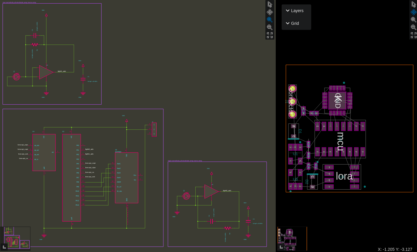
We can connect to supported bundles using the require statement and the pin assignment solver in JITX will either come up with a valid concrete pin assignment, or indicate that no solution is possible. Let's break down the require statements in the main module.
The following statement requests a bundle called light of type adc[2] from our instance of the microcontroller, mcu.
require light:adc[2] from mcu
Now light exists as a bundle of type adc[2] (i.e. two adc pins named light[0] and light[1]) associated with the mcu. Later, the pin solver will find two concrete pins on the mcu that supports adc, and replace light[0] and light[1] in the netlist with a reference to those pins. Because light is guaranteed to exist, we can use it like a real bundle and net the adc pins in the bundle to the outputs of our transimpedance amplifiers:
  net (high-sensitivity-photodiode.output light[0].adc)
  net (low-sensitivity-photodiode.output light[1].adc)
Similarly, we can require an i2c bundle, 4 gpio, and an spi-controller bundle from the MCU and connect them to the components on the board. Note that OCDB distinguishes between SPI controllers and peripherals and we used connect-spi (imported from ocdb/utils/connects) to make the connection instead of a net statement (because the bundles are different).
And here is our final design:
The solver is clever, and ensures that it doesn't reserve a pin for gpio that is required by and i2c or adc pin. You can play with this generator to test the capabilities of the solver for yourself. Furthermore supports and require works at the module level as well, so you can have a bundle supported by a collection of circuitry, not just by a component.
So now we have worked through from the fundamentals of JITX to a design built from reusable code. You should be able to do most things in JITX now - reach out if you have any questions!