Symbol
The symbol statement defines the mapping between a component's ports and the pins of a schematic symbol.
A pcb-component can have one or more schematic symbols associated with it. For the case where multiple schematic symbols are associated with a component, we consider each distinct schematic symbol a "Unit". For the single schematic symbol the "unit" connotation is implied.
Signature
  ; Single Symbol Unit Declaration
  symbol = <SYMB>( <PORT-1> => <SYMB>.<PIN-1>, <PORT-2> => <SYMB>.<PIN-2>, ... )

  ; Multi-Symbol Unit Declaration
  symbol :
    unit(<BANK-ID>) = <SYMB>(
      <PORT-1> => <SYMB>.<PIN-1>,
      <PORT-2> => <SYMB>.<PIN-2>,
      ...
      )
    ...

  ; With a Pin Property Table
  assign-symbol(<SYMB>)

  assign-symbols([
    <BANK-ID> => <SYMB-1>,
    <BANK-ID> => <SYMB-2>,
    ...
  ])
symbol =- This is an explicit mapping statement for a single schematic symbol unit. Notice that there is no<BANK-ID>in this declaration as the unit is implied.<SYMB>- This is a pcb-symbol definition.<PORT-1>- This is a port on the currentpcb-componentdefinition by ref.<PIN-1>- This is a pin of the<SYMB>definition. Note that we usedotnotation to access this pin definition.=>is a mapping operatorsymbol:- This is a method of providing multiple schematic symbol units for this component definition via explicit mapping.- The
<BANK-ID>is typically of typeInt|Ref. It is used to uniquely identify a particular schematic symbol unit.- In Altium - you would like see a fixed sub-symbol identifier as
A,B, etc. - In JITX - you can identify units as a number
0,1, etc or as aRefsymbol such aspower,config, etc
- In Altium - you would like see a fixed sub-symbol identifier as
- Notice that for each
unit()statement we use the same mapping syntax as for the single unit case. assign-symbol()- This is a utility function for constructing the mapping when the user has defined a pin-properties table.- The
<SYMB>argument is a pcb-symbol definition. assign-symbols()- Similar toassign-symbolbut this handles the multiple symbol unit case.- This function expects a tuple of mappings between the
<BANK-ID>and the<SYMB>
Usage
There are two primary ways to utilize the symbol statement:
- Explicit Mapping
- Pin Properties Table Mapping
Explicit Mapping
pcb-component op-amp :
  port supply : power
  port vin : diff-pair
  port vout : pin

  symbol = op-amp-sym(
    self.vin.P       => op-amp-sym.vin.P
    self.vin.N       => op-amp-sym.vin.N
    self.vout        => op-amp-sym.out
    self.supply.vdd  => op-amp-sym.v+
    self.supply.gnd  => op-amp-sym.v-
  )


pcb-symbol op-amp-sym :
  pin v- at Point(0.0, -2.0)
  pin v+ at Point(0.0, 2.0)
  pin vin.N at Point(-2.0, -1.0)
  pin vin.P at Point(-2.0, 1.0)
  pin out at Point(2.0, 0.0)

  ; More Symbol Geometry Here
  ...
In this example, we define the ports of the op-amp component as bundles and single pin ports. These ports don't match 1:1 with the symbol's pin declarations. This is an example of a case where an explicit symbol mapping statement is required.
The mapping statements self.vin.P => op-amp-sym.in+ are on single pins only. There is no way to map bundle to bundle between component port and symbol pins. If you were to try and do something like:
  symbol = op-amp-sym(
    self.vin       => op-amp-sym.vin
    ...
  )
You would see an exception like this:
Uncaught Exception: ... : Must map to a symbol pin with a single pin (received a pin bundle).
Further - this mapping function has the following expectations:
- Each component port must have a mapping
- If you were to forget a port in the mappings, this would elicit a
Uncaught Exception: ... : Every component pin must have an entry in a symbol mapping.error.
- If you were to forget a port in the mappings, this would elicit a
- Each port to symbol mapping must be unique.
- If you were to make two mappings that both referenced
self.vout, this would elicit aUncaught Exception: ... : A component pin is used multiple times in a mappingerror.
- If you were to make two mappings that both referenced
- Each schematic symbol pin is used in only one mapping.
- If you were to make two mappings with different component ports that each mapped to the same schematic symbol pin - this would elicit a
Uncaught Exception: ... : A symbol pin is used multiple times in a symbol mapping.error.
- If you were to make two mappings with different component ports that each mapped to the same schematic symbol pin - this would elicit a
Pin Properties Table
With the pin-properties table, we can simplify this mapping application by using the assign-symbol() command. With the pin-properties table, we can simplify this mapping application by using the assign-symbol() command.
pcb-component op-amp :

  pin-properties:
    [pin:Ref | pads:Int ...]
    [v-      | 1 ]
    [v+      | 2 ]
    [in+     | 3 ]
    [in-     | 4 ]
    [out     | 5 ]

  assign-symbol(op-amp-sym)


pcb-symbol op-amp-sym :
  pin v- at Point(0.0, -2.0)
  pin v+ at Point(0.0, 2.0)
  pin in+ at Point(-2.0, -1.0)
  pin in- at Point(-2.0, 1.0)
  pin out at Point(2.0, 0.0)

  ; More Symbol Geometry Here
  ...
In this example, we are leveraging the "Pin Properties" table to construct the port to symbol mapping automatically.
- Notice how we haven't defined any port statements for this component. The
pin-propertiesstatement handles defining any missing ports. - Notice that the
pincolumn in the table specifiesrefsymbols. Theserefsymbols must match with apinin thepcb-symboldefinition. This must be a 1:1 mapping.
Assuming that the ports that you want to define on the component match the pins on the pcb-symbol, this can be a convenient way to reduce duplication in the pcb-component definition.
Symbols are Internal to Components
The pcb-symbol assigned via the symbol statement is only used internally by the pcb-component definition. It is typically not possible nor useful for external entities to reference the symbol.
Further - there is no concept of "connecting" to a pcb-symbol. When constructing a circuit (net list) with the net statement, we can't connect to a pin of the pcb-symbol. We must connect to a port of the component.
Multi-part Symbols
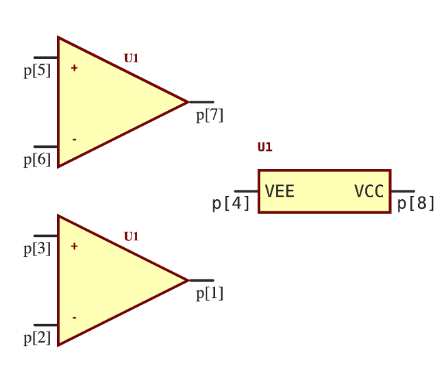
It is often useful to create symbols that have multiple constituent parts. For example, a dual operational amplifier like the LM358LV contains two independent operational amplifiers. JITX provides multi-part symbol support via the unit statement.
Unit Statement Example
Complete design example for multi-part symbols
public defstruct OpAmpBank :
  in+:JITXObject
  in-:JITXObject
  out:JITXObject

public defn make-multi-opamp-symbol (banks:Seqable<OpAmpBank>, VCC:Pin, VEE:Pin) :
  inside pcb-component:
    symbol :
      val psym = ocdb/utils/symbols/power-supply-sym
      unit(0) = psym(VCC => psym.vs+, VEE => psym.vs-)
      for (bank in banks, i in 1 to false) do :
        val sym = ocdb/utils/symbols/multi-op-amp-sym
        unit(i) = sym(
          in+(bank) => sym.vi+,
          in-(bank) => sym.vi-,
          out(bank) => sym.vo
        )
Notice that the unit statement takes a single Int argument as the index into the multi-part symbol array. You can then assign any symbol with the = assignment operator.
; Example use `make-multi-opamp-symbol`
;
pcb-component DualOpAmp:
  port VCC
  port VEE

  port in1+
  port in1-
  port out1

  port in2+
  port in2-
  port out2

  ...
  val banks = [
    OpAmpBank(in1+, in1-, out1),
    OpAmpBank(in2+, in2-, out2)
  ]
  make-multi-opamp-symbol(banks, VCC, VEE)
When invoked, this results in a component with 3 parts: a sub-part symbol for the power rails and 2 sub-parts for the op-amp symbols.