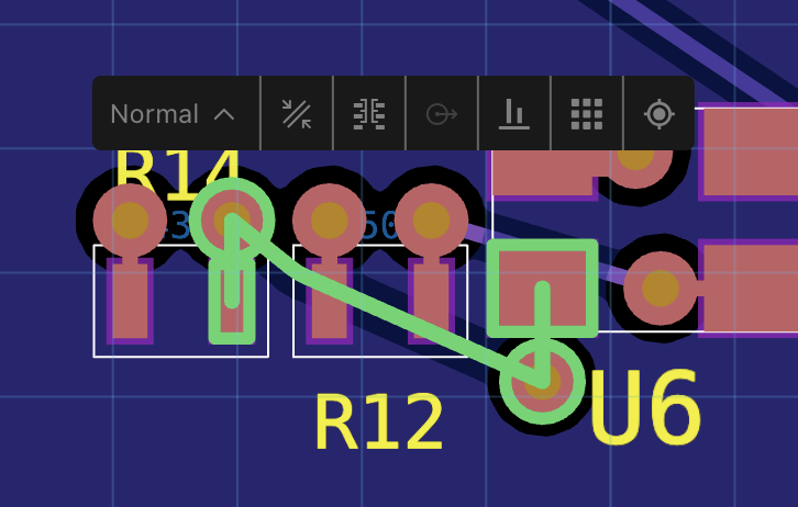
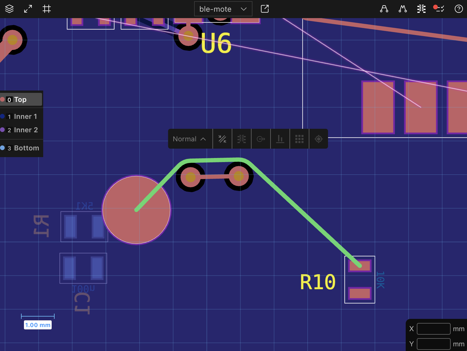
Edit Bar
The Edit Bar in JITX provides contextual options for modifying selected elements. When one or more elements are selected, the Edit Bar appears centered above the selection, offering a variety of menus and tools depending on the type of elements selected.
Edit Bar Actions
Route Type: Set the route type using the dropup menu.
 - Trace Width and Clearance: Adjust trace width and clearance for selected routes.
 - Via Properties: View and edit via type, layers, and jump to via definition in code.
 - Control Point Properties: Change the diameter of the selected control point.
 - Align Elements: Align selected elements by their center points along the appropriate axis.
 - Distribute Elements: Distribute selected elements evenly by their center points along the appropriate axis.
 - Location and Rotation: Display and edit the X, Y coordinates, and rotation angle of the selection.
Menus
Route Type
- Available: When one or more routes are selected.
-
Function: Set the route type for the selected routes using the drop-up menu. Options include:
- Normal: A standard route without additional properties. It does not apply any special constraints or modifications.
- Pour: The route becomes part of a copper pour on its layer. If no pour exists, a new pour is created to encompass the route.
Figure 2: The route becomes part of a copper pour. - Neckdown: The route follows neckdown properties, such as reduced trace width, defined by its routing structure, if it is associated with one from a topology.
Figure 3: A route with neckdown properties defined by its topology. - Length Matching: The route adheres to timing constraints set by its topology, ensuring that the total length meets specified requirements.
Figure 4: Routes following length matching constraints. - Adaptive: The route gradually changes width to match the size of its endpoints, ensuring smooth transitions between different trace widths.
Figure 5: An adaptive route adjusting its width to match endpoints. -
Displayed Name: The menu displays the route type for the selected route(s). If multiple routes with different types are selected, the menu displays 'Mixed'.
Trace Width and Clearance
- Available: When one or more routes are selected.
- Function: Adjust the trace width and clearance for the selected routes.
Via Properties
- Available: When one or more vias are selected.
- Function: View and edit properties for the selected vias:
- Display the via type and the layers it spans.
- Change the via type using the dropdown menu.
- Jump to the via definition in the code editor.
Control Point Properties
- Available: When one or more control points are selected.
- Function: Change the diameter of the selected control points.
Align Elements
- Available: When two or more elements are selected.
- Function: Align the selected elements by their center points. The axis with the largest separation of center points is chosen automatically.
Distribute Elements
- Available: When three or more elements are selected.
- Function: Distribute the selected elements evenly by their center points along an axis. The axis with the largest separation of center points is chosen automatically. The outermost elements remain in place, while intermediate elements are adjusted to produce even spacing.
Location and Rotation
- Available: Always available.
- Function: Display and edit the X, Y coordinates, and rotation angle of the selection.