Board View
The Board View in JITX provides a visual and interactive interface to arrange, route, and manage your PCB layout. This view allows you to control the placement of components, manage layers, configure routing settings, and ensure design rule compliance.
Toolbar

The Toolbar in the Board View includes buttons for toggling dialogs, managing routing modes, and performing layout operations. Below is a breakdown of the available commands and their functions.
Toolbar Commands
 - Toggle the layer table open and closed.
 - Fit the board to the screen.
 - Toggle the grid dialog open and closed.
 - Autoroute the selected objects.
 - Enters manual route mode and reveals three additional buttons:
 : Enter via mode to create and route vias.
 : Enter control point mode to create and route control points.
 : Enter differential insertion mode to create insertion points and route differential pairs.
- - Toggles the via dialog open and closed.

 - Toggle the progress report panel open and closed. A red circle indicates detected issues.
 - Toggle the hotkey panel open and closed.
Layer Table
The Layer Table allows you to manage the visibility and interaction priority of different board layers. Layers are organized by side (when applicable). Toggle the panel open and closed with D.
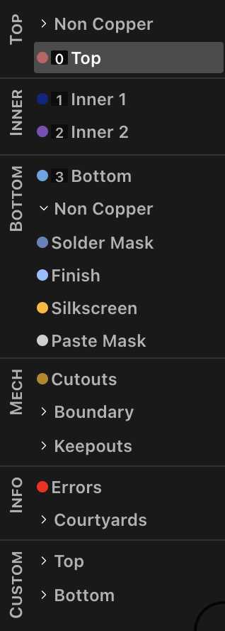
- Set an Active Layer: Displays the selected layer above other layers.
- Solo a Layer: Displays only the selected layer while hiding others.
- Hide a Layer: Hides the selected layer from view.
- Navigation Keybinds:
- Up One Copper Layer: W
- Down One Copper Layer: S
- Top Copper Layer: Shift+W
- Bottom Copper Layer: Shift+S
Grid Dialog
The Grid Dialog provides options to customize the grid settings in the Board View:
- Toggle Grid Visibility: Show or hide the grid on the board.
- Toggle Scale Indicator: Show or hide the scale indicator at the bottom right corner of the screen.
- Input a Custom Scale: Set a custom grid scale value and choose units (mm or mil). The default value is 0.1 mm. The chosen unit also reflects in the coordinates shown at the bottom left of the screen.
- Set Origin (X and Y): Set the origin point for the grid. A button is available to reset the origin to default.
Via Dialog
The Via Dialog lets you manage via settings for routing in the Board View. Toggle the dialog open and closed with V.
- Select a Via Definition: Choose a via definition from a dropdown that includes all via definitions associated with the design's board. The active via is used in all drag and auto-via operations. A button next to the dropdown opens the via definition in the code editor.
- View Via Properties: View properties of the selected via definition in the dropdown below.
Progress Report Panel
The Progress Report Panel in the Board View provides a detailed overview of the routing progress and signal integrity violations:
- Remaining Routes: Shows the remaining routes and pin-assigned routes that need to be completed.
- Signal Integrity Violations: Describes any violations detected for elements involved in signal integrity. Examples of some issues include unmet timing or loss constraints, bad topologies, and invalid overlaps.
Other Visual Toggles
- Help menu: /, ?
- Ratsnest: O
- Pin labels: L
- Pour outlines: P