Design Hierarchy#
In JITX, we can think of an electronic circuit as a hierarchical graph of components and modules. We call this graph the circuit graph. Understanding the circuit graph is critical to understanding how the code, schematic, and board work together in a complete design.
This hierarchical graph concept is a pretty common trait in many CAD tools. Just to name a few:
Tools like Unity and Blender use a Scene Graph to arrange models, cameras, and other objects.
Solidworks uses a Design Tree for capturing the relationships between components and assemblies.
Most ECAD tools have this kind of hierarchical graph as well but the schematic capture tools can make it a bit more opaque.
For many tools, each schematic sheet is an implicit “module” of the design.
Multiple sheets are combined together to form a complete design.
Multiple circuits might end up on one sheet that might otherwise be better off as independent modules.
Coming from Altium, you will probably be familiar with multi-channel hierarchical designs.
Circuits & Components#
The circuit graph consists of two main types of nodes:
Circuit nodes - Instantiated with objects derived from Circuit.
Component nodes - Instantiated with objects derived from Component.
FPGA Designers - The following will likely feel pretty familiar to you. Whether you are coming from VHDL, Verilog, or others, the modular structure of a design in JITX will mimic the structural architecture of many HDL designs.
Instances and Classes#
In Python, to define a new type we will typically declare a new class:
class Fruit:
  def __init__(self, name):
    self.name = name

class Apple(Fruit):
  def __init__(self):
    super().__init__("Cosmic Crisp")
In JITX, we define new class types to create the definitions for a new component or circuit. Here is an example for
defining a new component:
class NE555(Component):
  VDD = Port()
  GND = Port()
  ...
We derive from the
Componentbase type.We define a set of Port objects using class attributes.
Notice that in this example there is no __init__ method. In this case, NE555 is acting more like a dataclass definition.
We instantiate an instance of this new NE555 class in a new type derived from Circuit:
class OneShotTimer(Circuit):
  supply = Power()

  timer = NE555()

  GND = supply.Vn + timer.GND
Power is a type of
Portand defines connection points to this circuit.The
timerobject is instantiated declaratively as a class attribute. At build time, this gets converted into aNE555instance in the circuit.The
+operator is used to construct a net connection between the portssupply.Vnandtimer.GND. This net is then assigned to a class attributeGND. At build time, this netGNDwill be instantiated as part of this circuit.
The root node of the circuit graph will always be an instance of a class derived from Circuit. The root node will be the parent of any number of child nodes. Circuit and Component derived nodes will define the devices and structure of the circuit, but many other node types will be present in the circuit graph to describe things like:
Ports
Nets
Topologies
Properties
and many others
Creating an Array of Instances#
If we want to create an array of instances of components or circuits, we can use one of a number
of python collection types, like list, tuple, or dict:
import numpy as np

class OneShotTimer(Circuit):
  # Accepted
  timers = [NE555() for _ in range(4)]            # list
  timers = {i:NE555() for i in range(4)}          # dict
  timers = tuple(NE555() for _ in range(4))       # tuple
  timers = np.array([NE555() for i in range(4)])  # Numpy Array

  # These do NOT work
  timers = (NE555() for i in range(4))            # Generator
  timers = set(NE555() for i in range(4))         # Set (or frozenset)
The set and frozenset collections don’t generally enforce any ordering
of elements and so they are not supported in the JITX framework.
Caution - The above example uses list, dict, and tuple comprehensions to create arrays of component or circuit instances - but there are dragons here. See the section on List Comprehension Scope for important caveats.
Once created, we can reference the component instances in the array like we normally
would in python with the __getitem__ accessor (eg, timers[0]). This includes negative indexing and slice operators.
Imperative Style#
In the previous examples, we have used a declarative style to define the components and other entities that are owned by a Circuit type. We can also use the __init__ constructor to create our circuit in a more imperative style. For example:
class OneShotTimer(Circuit):

  def __init__(self):
    self.supply = Power()
    self.timer = NE555()
    self.GND = self.supply.Vn + self.timer.GND
This is an equivalent representation for this circuit. Notice that all of the nodes in this circuit graph must be assigned as attributes to self. If an object is not assigned to self - this will produce a warning in the output log. For example:
def __init__(self):
  ...
  # Original:
  #self.GND = self.supply.Vn + self.timer.GND
  # Mistake:
  GND = self.supply.Vn + self.timer.GND
This will elicit a warning like this:
WARNING:jitx._structural:Reference to structural object Net() at main.py:33 lost during instantiation, it likely needs to be assigned to an object.
This is trying to prod you to add GND as an attribute to self (or some other appropriate node in the circuit graph). The main.py:33 means that the offending object is found
on line 33 of the main.py file.
Cyclic Circuit Graphs#
Because this graph is describing hardware, we have to be careful about defining cycles in our circuit. For example, a recursive definition like this:
class A(Circuit):
  def __init__(self):
    self.obj = B()

class B(Circuit):
  def __init__(self):
    self.obj = A()
Will not work - it will result in a stack overflow as the system attempts to continuously instantiate A then B then A again for
ever. In general, recursively defined circuits are hard to get right and use properly. For more information, see Recursion & Cyclic Circuit Graphs
Circuits in the Schematic#
The circuit graph plays an important role in schematic visualization as well.
Each Circuit has an implicit SchematicGroup. All of the child component/circuit instances of a Circuit are added to that implicit schematic group by default. This implicit schematic group provides a reference point - dare we say, a grounding - between code text and visual schematic medium.
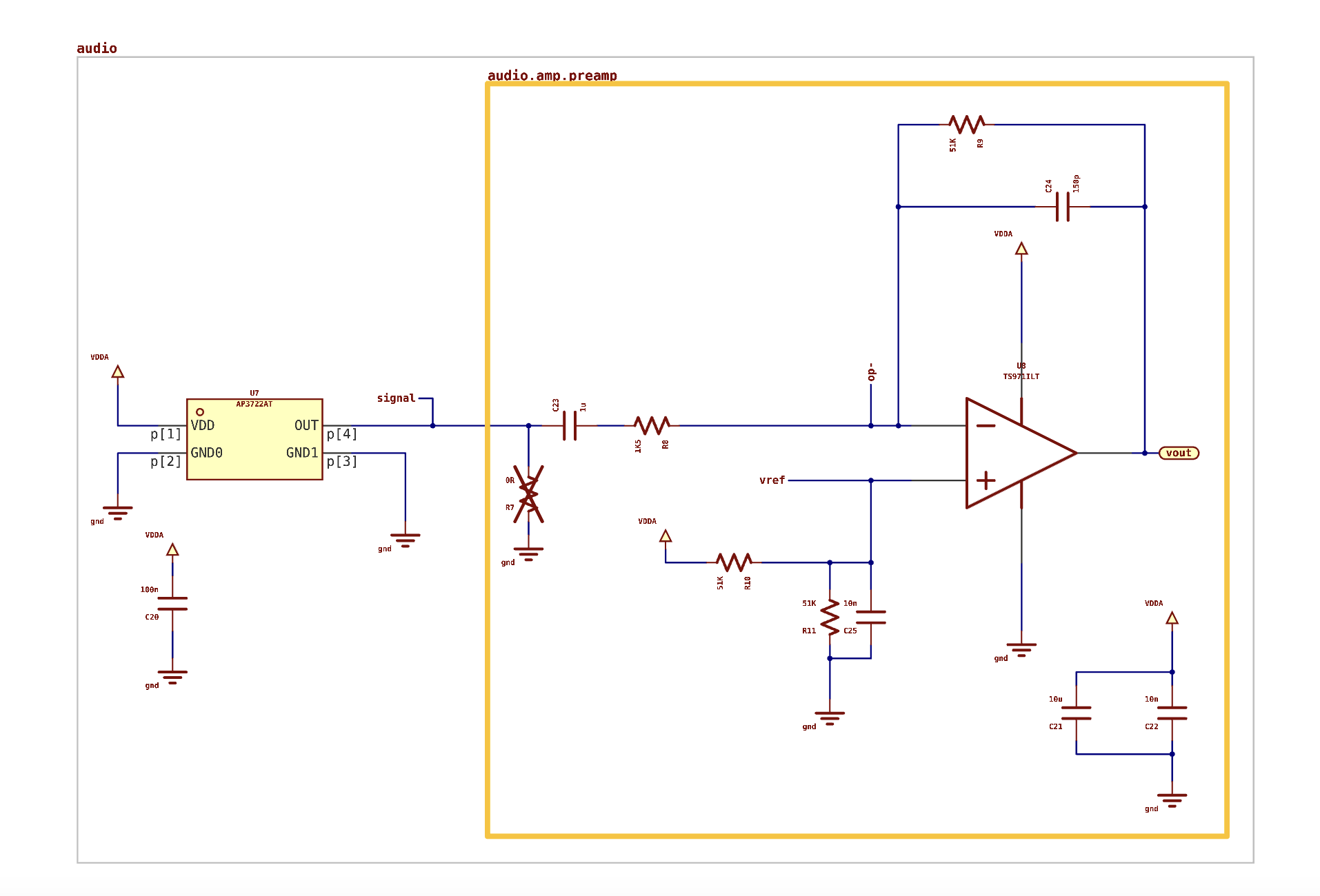
Schematic groups are a method of organizing our schematic sheets with like circuits. They also provide a natural boundary between circuits that are not intended to interact.
In the image above, notice that the schematic groups are labeled with a dot notation. The audio.amp.preamp label indicates that the orange bounded circuit is the preamp instance inside the audio.amp parent circuit. The audio.amp circuit is a child of the audio grand-parent. This labeling allows us to easily map the circuits shown in the schematic to the python code in the source files.