# Substrate & Stackup
The [Substrate](../../api/jitx.substrate.md#jitx.substrate.Substrate) is a class that encapsulates the stackup, fabrication constraints, routing structures, vias, and other physical features that define the primitives of a PCB design. This class is intended to be included at the top-level of a design and be referenced at any point in the design tree. This allows both the end-user and library developers to reference the substrate when programmatically constructing circuits and layouts.
## Substrate
If we reference the [SampleSubstrate](../../api/jitx.sample.md#jitx.sample.SampleSubstrate), we can see the basic structure
for a substrate:
```python
class SampleSubstrate(Substrate):
"""Sample substrate using a two layer stackup and the sample fabrication
constraints."""
stackup = SampleTwoLayerStackup()
constraints = SampleFabConstraints()
class MicroVia(Via):
...
RS_50 = RoutingStructure(
impedance = 50 * ohm,
layers = symmetric_routing_layers(...)
)
DRS_100 = DifferentialRoutingStructure(
name = "100 Ohm Differential Routing Structure",
impedance = 100 * ohm,
layers = symmetric_routing_layers(...)
)
```
The `stackup` and `constraints` attributes are required for a substrate. The via and routing structure definitions are optional features. We can add as many via definitions as needed for our design.
The routing structures are registered with the substrate associated with a characteristic impedance. The idea is that the user can use the [routing_structure](../../api/jitx.substrate.md#jitx.substrate.Substrate.routing_structure) and [differential_routing_structure](../../api/jitx.substrate.md#jitx.substrate.Substrate.differential_routing_structure) methods to lookup routing structures by impedance. In this example, we have a 50Ω single-ended and a 100Ω differential routing structure. For example:
```python
import jitx
class SomeCircuit(jitx.Circuit):
def __init__(self):
rs = jitx.current.substrate.routing_structure(50.0)
```
The idea here is that we can abstract the details of a particular substrate from the code that needs to know about vias, routing structures, and other primitives. The `routing_structure` method allows us to query the substrate for the current design for an impedance controlled structure. Whether you are writing a custom circuit for this design, or are developing a general use library to be used in many designs, this provides a common way to query these necessary structures without needing to know the details about the substrate.
## Stackup
The [Stackup](../../api/jitx.stackup.md#jitx.stackup.Stackup) defines the laminated layers of conductors and dielectrics that make up a PCB. This stackup defines each layers thickness and order, as well as other properties that relate to the physical characteristics of each layer.
The stackup is constructed using the following [Material](../../api/jitx.stackup.md#jitx.stackup.Material) types:
* [Conductor](../../api/jitx.stackup.md#jitx.stackup.Conductor) - The metal layers that conduct signals.
* [Dielectric](../../api/jitx.stackup.md#jitx.stackup.Dielectric) - The non-conductive layers that provide isolation between layers.
We build the stackup by declaring an **ordered sequence of layers** inside a class derived from [Stackup](../../api/jitx.stackup.md#jitx.stackup.Stackup). Here is a simple 2-layer example:
```python
from jitx.stackup import Dielectric, Conductor, Stackup
class LPIMask(Dielectric):
thickness = 0.1 # mm
class FR4Core(Dielectric):
thickness = 1.5 # mm
class Cu1oz(Conductor):
thickness = 0.035 # mm
class Basic_Two_Layer(Stackup):
top_solder_mask = LPIMask()
top_copper = Cu1oz()
core = FR4Core()
bottom_copper = Cu1oz()
bottom_solder_mask = LPIMask()
```
This results in the following stackup representation in the physical design view of the board:
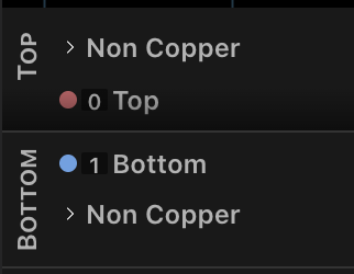
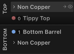
Notice that we get default names `Top` and `Bottom` for the copper layers. To customize this, we can add names for each of the `Cu1oz` instantiations:
```python
...
top_copper = Cu1oz(name="Tippy Top")
core = FR4Core()
bottom_copper = Cu1oz(name="Bottom Barrel")
...
```
### Multi-layer Stackup
In most modern designs, you will likely need more than 2 layers. If we were to build on the previous example to create a 4-layer board, it might look something like this:
```python
class FR4Prepreg(Dielectric):
thickness = 0.25 # mm
class Basic_Four_Layer(Stackup):
top_solder_mask = LPIMask()
top_copper = Cu1oz()
pp1 = FR4Prepreg()
gnd_copper = Cu1oz()
core = FR4Core()
vdd_copper = Cu1oz()
pp2 = FR4Prepreg()
bottom_copper = Cu1oz()
bottom_solder_mask = LPIMask()
```
Similar structure to the 2-layer board with just more layers. Now if you imagine taking this to 6, 8, or more layers, this ends up being a lot of typing. We can take advantage of the symmetry present in most PCB stackups to reduce the amount of typing we need to do:
```python
from jitx.stackup import Dielectric, Conductor, Symmetric
class Symmetric_Four_Layer(Symmetric):
solder_mask = LPIMask()
ext_copper = Cu1oz()
pp = FR4Prepreg()
inner_copper = Cu1oz()
core = FR4Core()
```
This creates a 4-layer stackup with the same layer entries as `Basic_Four_Layer`.
## Vias
In JITX, each design can use a finite set of via types. We must define these via types in the `Substrate` class.
```python
import jitx
from jitx.layerindex import Side
from jitx.via import Via, ViaType
class SampleSubstrate(jitx.Substrate):
"""Sample substrate using a two layer stackup and the sample fabrication
constraints."""
...
class MicroVia(Via):
start_layer = 0
stop_layer = 1
diameter = 0.3
hole_diameter = 0.1
filled = True
tented = Side.Top
type = ViaType.LaserDrill
class THVia(Via):
start_layer = Side.Top
stop_layer = Side.Bottom
diameter = 0.45
hole_diameter = 0.3
type = ViaType.MechanicalDrill
```
### Via Properties
Each via definition supports several properties that control its manufacturing and behavior:
**`type`**: Specifies the drilling method:
* `ViaType.MechanicalDrill`: Standard mechanical drilling. Used for through-hole vias and larger buried vias. Typical minimum hole diameter is around 0.2–0.3 mm.
* `ViaType.LaserDrill`: Laser-drilled microvias. Used for fine-pitch layer transitions (typically spanning 1–2 layers). Supports smaller hole diameters (down to ~0.075 mm) but is limited in the number of layers it can span.
**`filled`**: When `True`, the via hole is filled with conductive or non-conductive epoxy. Filled vias are required for via-in-pad designs where a component pad sits directly on top of the via. Without filling, solder can wick down through the hole during reflow, creating unreliable joints.
**`tented`**: Controls whether soldermask covers the via. Can be set to `True` (both sides), `Side.Top`, or `Side.Bottom` to tent specific sides. Tenting prevents solder from flowing into the via and protects against accidental shorts.
**`via_in_pad`**: When `True`, indicates the via is designed to be placed directly under a component pad. Typically used together with `filled = True`.
Here are examples illustrating common via configurations:
```python
from jitx.via import Via, ViaType
from jitx.layerindex import Side
class THVia(Via):
"""Standard through-hole via: mechanically drilled, spanning all layers."""
type = ViaType.MechanicalDrill
start_layer = Side.Top
stop_layer = Side.Bottom
diameter = 0.45
hole_diameter = 0.3
class FilledVia(Via):
"""Filled and tented via suitable for via-in-pad designs."""
type = ViaType.MechanicalDrill
start_layer = Side.Top
stop_layer = Side.Bottom
diameter = 0.45
hole_diameter = 0.3
filled = True
tented = True
via_in_pad = True
class MicroVia(Via):
"""Laser-drilled microvia spanning top two layers only."""
type = ViaType.LaserDrill
start_layer = 0
stop_layer = 1
diameter = 0.356
hole_diameter = 0.178
filled = True
via_in_pad = True
```
In the above definitions, the `Side.Top` and `Side.Bottom` enumerated values resolve to `0` and `-1` integer values, respectively.
Via layer indices count conductor layers only; dielectric layers, the solder masks included, take no index. They index the conductors from the top down the way Python indexes a list: `0` is the top conductor and `-1` the bottom, so in `Basic_Four_Layer` above `gnd_copper` is `1` or `-3`.
The indices are absolute in the board (see [Via](../../api/jitx.via.md#jitx.via.Via)): `0` is always the top conductor, even when the via, or the circuit that places it, is on the bottom side or is flipped in the board view. A land pattern’s pads move to the bottom with their component, because the component is mounted on one side. A via is a hole drilled between particular layers of the stackup, so it keeps the span its definition names. A via for the bottom of the board needs its own definition on bottom layers, such as `start_layer = -2` and `stop_layer = -1` for the bottom two conductors.
The keys of [Via.diameters](../../api/jitx.via.md#jitx.via.Via.diameters) are layer indices too, or tuples of them. A key outside the board’s conductors raises an error when the design is translated, as does a layer that appears in two keys, such as `1` and `(1, 2)`, or under both of its indices, such as `0` and `-4` on a four-conductor board.
To reference a via in code, we need to reference the substrate type by name:
```python
class SomeCircuit(jitx.Circuit):
def __init__(self):
# Via Type
viaType = SampleSubstrate.THVia
# Instantiating the Via
self.codePlacedVia = viaType().at(2.0, 3.0)
```
## Via Structures
When a signal transitions between layers of a PCB, a bare via on its own can introduce impedance discontinuities and crosstalk. A **via structure** wraps the signal via with surrounding ground vias (a “ground cage”), anti-pad keepout regions and, for a differential pair, optional pair insertion points to create a controlled, well-shielded layer transition.
JITX provides via structure classes in the [jitxlib.via_structures](../../jitxlib-standard/jitxlib.via_structures.md#module-jitxlib.via_structures) module. The key classes are:
* [SingleViaStructure](../../jitxlib-standard/jitxlib.via_structures.md#jitxlib.via_structures.SingleViaStructure): For single-ended signals.
* [DifferentialViaStructure](../../jitxlib-standard/jitxlib.via_structures.md#jitxlib.via_structures.DifferentialViaStructure): For differential pair signals.
A via structure is a [Circuit](../../api/jitx.circuit.md#jitx.circuit.Circuit) with signal ports (`sig_in`, `sig_out`) and a `COMMON` (ground) port. You instantiate it and wire it into your circuit with ordinary nets, just like any other component.
### Ground Cages
A ground cage is a ring of vias surrounding the signal via to provide shielding. The [PolarViaGroundCage](../../jitxlib-standard/jitxlib.via_structures.md#jitxlib.via_structures.PolarViaGroundCage) class arranges ground vias in a circular pattern around the signal via.
`PolarViaGroundCage` is a dataclass: you create instances by passing arguments directly to the constructor:
```python
from jitxlib.via_structures import PolarViaGroundCage
cage = PolarViaGroundCage(
SampleSubstrate.THVia, # via_def: which Via type to use for the cage vias
count=12, # total positions in the circular pattern
radius=0.85, # radius in mm from the signal via center
skips=[0, 3, 6, 9], # indices to leave empty (for trace routing escape)
)
```
The `skips` parameter is a list of indices (0-based, up to `count - 1`) indicating positions in the circular pattern where no via should be placed. This is how you create gaps for signal traces to enter and exit the structure.
Optional parameters:
* `theta`: Starting angle in degrees (default `0.0`, pointing right along the X axis).
* `pose`: A [Transform](../../api/jitx.transform.md#jitx.transform.Transform) to offset the entire cage relative to the via structure origin.
#### NOTE
### Note
`PolarViaGroundCage` must be **instantiated** with its constructor arguments. Defining a subclass with class-level attributes will not work because the base class is a dataclass whose `__init__` expects positional arguments.
### Anti-Pads
An anti-pad is a keepout region that keeps poured copper, such as a ground plane, away from the signal via, so the plane can’t short to it. On a board with inner planes it goes on those layers; the two-layer sample board in these examples has only layers 0 and 1. Use [SimpleAntiPad](../../jitxlib-standard/jitxlib.via_structures.md#jitxlib.via_structures.SimpleAntiPad) to define one:
```python
from jitx.layerindex import LayerSet
from jitx.shapes.composites import double_chipped_circle
from jitxlib.via_structures import SimpleAntiPad
antipad = SimpleAntiPad(
double_chipped_circle(0.5, 0.4), # keepout shape
LayerSet.range(start=0, through=1), # layers to apply to
)
```
The shape is placed as a [KeepOut](../../api/jitx.feature.md#jitx.feature.KeepOut) on the specified layers. The `pose` parameter (default identity) allows you to offset the anti-pad relative to the via structure origin.
### Insertion Points
Insertion points apply to differential via structures. [DifferentialViaStructure](../../jitxlib-standard/jitxlib.via_structures.md#jitxlib.via_structures.DifferentialViaStructure) takes two optional arguments, `enterOn` and `exitOn`. Each is a layer index, or an `InsertionPlacement(layer, offset)` from the same module. Each one places a pair insertion point on that layer, beside the vias (half the via pitch away unless you give an offset), and routes its two uncoupled ends to the P and N vias, so the pair stays coupled up to the structure. [SingleViaStructure](../../jitxlib-standard/jitxlib.via_structures.md#jitxlib.via_structures.SingleViaStructure) has no insertion points.
### Single-Ended Via Structure
A [SingleViaStructure](../../jitxlib-standard/jitxlib.via_structures.md#jitxlib.via_structures.SingleViaStructure) creates a shielded layer transition for a single-ended signal. It has three ports:
* `sig_in`: Signal input (single [Port](../../api/jitx.net.md#jitx.net.Port))
* `sig_out`: Signal output (single [Port](../../api/jitx.net.md#jitx.net.Port))
* `COMMON`: Ground connection (single [Port](../../api/jitx.net.md#jitx.net.Port))
Here is an example that instantiates a single-ended via structure and wires it between two components, with the parts themselves left out (`...`):
```python
from jitx.circuit import Circuit
from jitx.layerindex import LayerSet
from jitx.net import Topology
from jitx.sample import SampleSubstrate
from jitx.shapes.composites import double_chipped_circle
from jitx.si import Constrain, PinModel
from jitxlib.via_structures import PolarViaGroundCage, SimpleAntiPad, SingleViaStructure
class SignalVia(SampleSubstrate.MicroVia):
# Delay (s) and loss (dB) from layer 0 to layer 1. Example values:
# take yours from your fabricator's via model or a simulation.
models = {(0, 1): PinModel(delay=7e-12, loss=0.05)}
class MyCircuit(Circuit):
def __init__(self):
...
self.ssvia = SingleViaStructure(
SignalVia,
ground_cages=[
PolarViaGroundCage(
SampleSubstrate.THVia,
count=12,
radius=0.85,
skips=[0, 2, 3, 4, 6, 8, 9, 10],
)
],
antipads=[SimpleAntiPad(double_chipped_circle(0.5, 0.4), LayerSet.range(start=0, through=1))],
)
# Wire the signal through the via structure with plain nets
self.sig_nets = [self.comp1.pin + self.ssvia.sig_in, self.ssvia.sig_out + self.comp2.pin]
# Connect the ground cage to the ground net
self.GND = self.comp1.gnd + self.comp2.gnd + self.ssvia.COMMON
self.cst = Constrain(Topology(self.comp1.pin, self.comp2.pin)).timing(1e-9).structure(SampleSubstrate.RS_50)
```
Inside the structure, `sig_in` and `sig_out` both connect to the signal via, `ssvia.signal_via`, so the signal path runs `comp1 → sig_in → [via] → sig_out → comp2`. The `COMMON` port connects all the ground cage vias to your ground net.
The constraint names the outer pads, `comp1.pin` and `comp2.pin`, as any [signal integrity constraint](../SI/constraints.md) does. Once the path is routed through the signal via, from `comp1` on layer 0 to `comp2` on layer 1 (the bottom of the two-layer sample board), the constraint measures across the structure, and the measured delay includes the `SignalVia` model. With both parts on layer 0, the same routes measured no delay from the via.
### Differential Via Structure
A [DifferentialViaStructure](../../jitxlib-standard/jitxlib.via_structures.md#jitxlib.via_structures.DifferentialViaStructure) creates a shielded layer transition for a differential pair. It has the same three ports, but `sig_in` and `sig_out` are [DiffPair](../../api/jitx.net.md#jitx.net.DiffPair) ports instead of single ports. It also takes a `pitch` parameter specifying the distance between the P and N signal vias.
```python
from jitx.net import DiffPair
from jitx.shapes.composites import double_notch_rectangle
from jitxlib.via_structures import DifferentialViaStructure, PolarViaGroundCage, SimpleAntiPad
class MyDiffCircuit(Circuit):
diffvia = DifferentialViaStructure(
SampleSubstrate.MicroVia, # via definition (or a tuple of two for separate P/N vias)
pitch=0.8, # distance between P and N vias in mm
ground_cages=[
PolarViaGroundCage(
SampleSubstrate.THVia,
count=12,
radius=0.85,
skips=[0, 2, 3, 4, 6, 8, 9, 10],
)
],
antipads=[
SimpleAntiPad(
double_notch_rectangle(1.5, 0.85, 0.45, 0.15),
LayerSet.range(start=0, through=1),
)
],
)
def __init__(self):
...
# Wire the pair through the via structure with plain nets
self.sig_nets = [self.dp_in + self.diffvia.sig_in, self.diffvia.sig_out + self.dp_out]
# Ground cage connection
self.GND = self.gnd_pin1 + self.gnd_pin2 + self.diffvia.COMMON
```
If the P and N signals require different via definitions, pass a tuple:
```python
diffvia = DifferentialViaStructure(
(MySubstrate.MicroViaP, MySubstrate.MicroViaN),
pitch=0.8,
ground_cages=[...],
antipads=[...],
)
```
### Multiple Via Structures
For bus signals, you can create multiple via structure instances using a list comprehension:
```python
from jitx.net import Net
class BusCircuit(Circuit):
BUS_WIDTH = 4
vias = [
SingleViaStructure(
SampleSubstrate.MicroVia,
ground_cages=[
PolarViaGroundCage(SampleSubstrate.THVia, count=12, radius=0.85, skips=[0, 6])
],
antipads=[
SimpleAntiPad(double_chipped_circle(0.5, 0.4), LayerSet.range(start=0, through=1))
],
)
for _ in range(BUS_WIDTH)
]
def __init__(self):
...
self.nets = []
for i in range(self.BUS_WIDTH):
self.nets.append(self.comp1.pins[i] + self.vias[i].sig_in)
self.nets.append(self.vias[i].sig_out + self.comp2.pins[i])
self.GND = Net([self.comp1.gnd, self.comp2.gnd] + [v.COMMON for v in self.vias])
```